Article Text

Abstract
Objectives—(a) To determine the force-time trace that occurs when a spring mounted simulated upper jaw is impacted; (b) to examine if mouthguards of variable quality have significant influence on such force-time traces; (c) to attempt to relate physical events to the profile of the force-time traces recorded.
Methods—A simulated jaw, consisting of ceramic teeth inserted into a hard rubber arch reinforced with a composite jawbone, was fitted with various mouthguards as part of a previous round robin study. A clinical assessment distinguished good, bad, and poor mouthguards, and these were each fitted to the jaw, which was then submitted to instrumental impact tests under conditions expected to produce tooth fractures. The force-time trace was recorded for such impact events.
Results—The spring mounting method caused two distinct peaks in the force-time trace. The initial one was related to inertia effects and showed an increase in magnitude with impactor velocity as expected. The second peak showed features that were related to the differences in the mouthguards selected.
Conclusions—The use of a force washer within a conical ended impactor enabled force-time traces to be recorded during the impact of a spring mounted simulated jaw fitted with mouthguards of variable quality. The spring mounting system causes an initial inertial peak followed by a second peak once the spring mount has fully compressed. Good fitting guards, which keep most teeth intact, result in high stiffness targets that in turn generate high reaction forces in the impactor. If the spring mounting is omitted, the two peaks are combined to give even higher reaction forces. The force-time trace offers some potential for assessing both overall mouthguard performance and individual events during the impact sequence. Mouthguards with good retention to the jaw remained attached during the impact event and helped to preserve the structural integrity of the target. This in turn developed high forces in the second part of the force-time trace. Guards that detached during impact and allowed tooth fractures showed lower forces in the second part of the test. The force profile measured offered some quantitative support to, and agreement with, the observed clinical quality of the mouthguards.
- mouthguard
- teeth
- dentition
- impact
Statistics from Altmetric.com
The recent development of a simplified jaw model, which uses a rubber arch, ceramic peg inserts, and a rebated inlay of light cured composite, has allowed the effectiveness of custom made mouthguards to be assessed under damaging impact conditions chosen to replicate the clinical observation of occasional tooth fracture and rare jaw bone fracture.1, 2 For these comparative purposes, it is not essential that the fracture toughness values of the inserts and inlays match their in vivo equivalents.
The ceramic pegs, which fit into blind sockets in the rubber arch, represent simplified tooth forms that may be amenable to future finite element analysis. The rebated composite inlay represents the upper jaw bone and the hard rubber is assumed to simulate the viscoelastic mounting of the teeth in the maxillary sockets. In addition, the standard jaw is designed to be mounted in a spring loaded device that simulates the instant recoil at the early stage of a frontal impact followed by a dead stop, which simulates the limit to the maximum backwards head movement under impact. Figure 1⇓ shows details. Mouthguards may be manufactured to fit the standard jaw by taking a normal dental impression and thermoforming an orthodontic mouthguard using “best current practice”. No standard or licensing is needed to manufacture such devices, although a draft British Standard has recently been delayed because of uncertainties about its precise role.
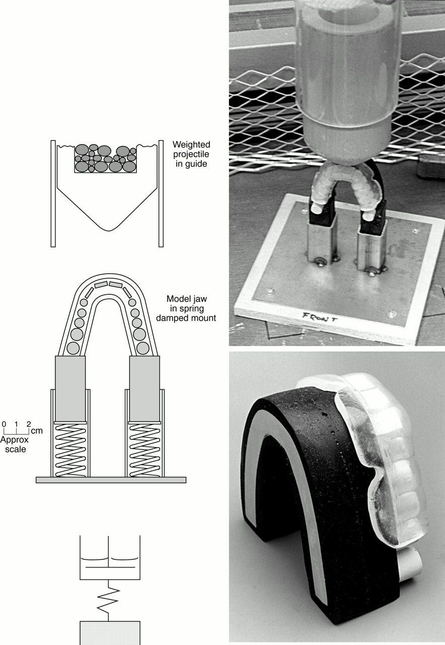
Impact set up for the standard jaw and indentor.
Hence the interpretation of “best current practice” shows much variation in design. A recent round robin trial conducted using the standard jaw revealed the variation between the mouthguards produced by 15 dental laboratories in the United Kingdom.3 Considerable variations in the volume of material used, its precise distribution within the guard, and the finishing details of the guard were assessed by an experienced clinician. The level of guard retention was assessed manually on the returned model and when it was fitted to the test jaw. The number of broken teeth observed after testing also showed considerable differences between manufacturers and gives a semiquantitative estimate of relative performance. Three guards were selected for this investigation as follows:
D—a poorly made guard with poor retention and poor impact performance;
L2—a well made guard with excellent retention and impact performance but probably uncomfortable because of the large volume of materials used;
P2—a well made guard which was probably the most comfortable because of the low volume of material used and with acceptable impact performance.
These variations represent those likely to occur within the dental laboratory trade in which materials and designs are unrestricted. Table 1⇓ shows previously published details, and fig 2⇓ shows typical examples. All the mouthguards produced in the round robin trial may be viewed at their web site.4
Test results

Typical examples of mouthguards. (A) A bulky guard; (B) poor edge finish; (C) internal air bubbles; (D) excellent.
The objective of this work was to examine whether the qualitative and semiquantitative variations in performance of the most widely varying guards taken from the round robin trial gave equivalent and quantifiable differences in force-time profiles when tested on an established and fully calibrated instrumented impact test machine.
Experimental
The conical ended, free falling indentor used in the previous work was replaced by an instrumented version having the same hardwood nose of identical profile but modified to include a piezoelectric force cell within its plastic body such that a force signal could be monitored through a trailing lead during the impact event (fig 3⇓). Although slightly heavier than the original indentor, the range of speeds used covered the same impact energy used in all previous work. A split guide tube was needed to allow the output wire free travel, and the usual spring loaded mounting bracket was used to support the jaw and mouthguard assembly (fig 1⇑).
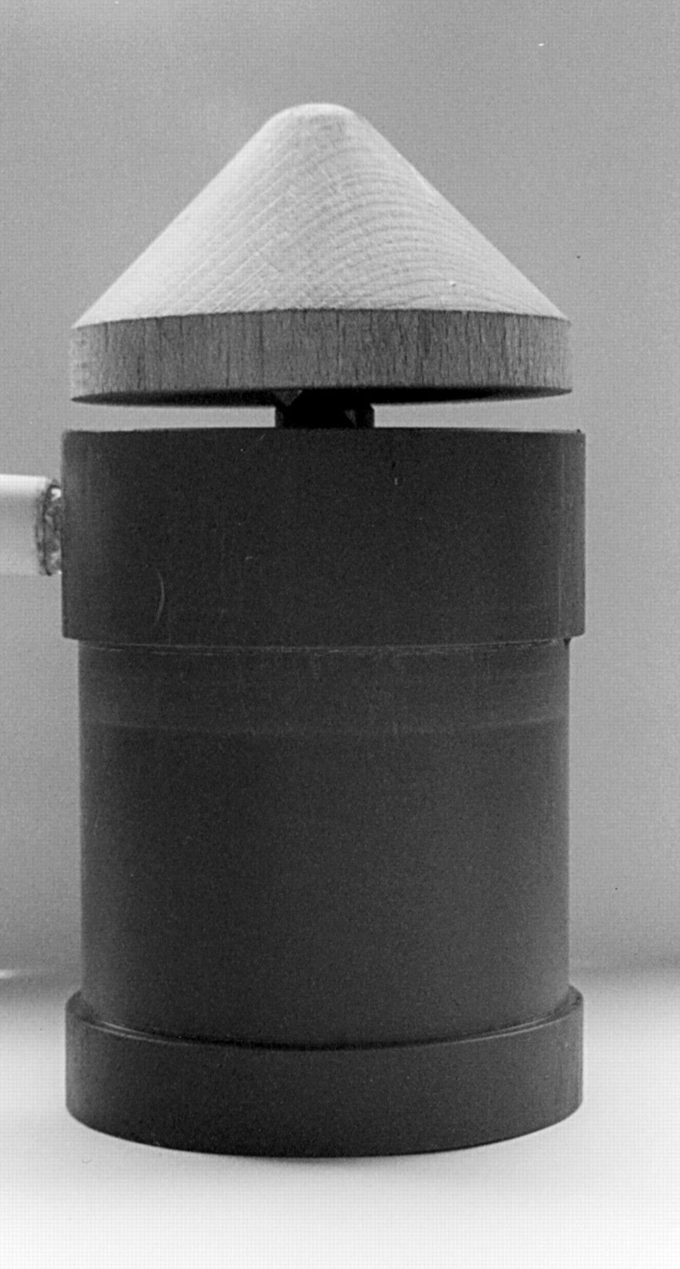
Modified indentor with central load washer.
Excellent agreement between this and previous studies with regard to the incidence of broken teeth and broken jaws was obtained. Hence it was possible to analyse the forces obtained from the instrumentation with some confidence. The output trace from the force cell was displayed on an oscilloscope and stored electronically. This enabled a detailed force-time trace to be produced after each impact event.
Results
Figure 4⇓ shows a compilation of the force-time traces. Each run was repeated three times, and excellent reproducibility in terms of force-time profiles and number of broken teeth was observed. It is not appropriate to average out these profiles. However, the profile that contained the median values of maximum forces was selected for comparison. The equipment automatically rescales the output, and the graph shown bottom right has a slightly larger scale value.

Force-time traces at various impact velocities for mouthguards P2, D, and L2.
It should be emphasised that the loads shown are those produced within the impacting device and not those in the mouthguard. Hence interpretation of the clinical implications requires careful consideration.
Discussion
The assembly can be modelled as an impact compression of a dashpot in series with an elastic compression coil spring that becomes infinitely stiff after a certain level of compression as shown in fig 1⇑. This behaviour is similar to a car suspension consisting of a coil spring, a shock absorber, and a dead stop, although the spring and the damper are usually arranged in parallel in this case. The rubber arch with its teeth and mouthguard behaves as the dashpot, which must be accelerated up to the impact speed while the coil support springs are undergoing compression.
The rigidity of the assembly is influenced by the presence of the mouthguard and the teeth. As will be shown below, impact events in which the mouthguard and/or teeth were missing gave significantly different responses. A stiff assembly is equivalent to having a more viscous fluid in the dashpot part of the schematic model (fig 1⇑). Once the spring has fully compressed, the assembly behaves as a simple dashpot under impact compression.
It has been recognised previously5 that such spring loaded impact targets respond in a particular way in response to Newton's second law. The assembly must be accelerated up to the impactor speed, and during this acceleration the force generated is proportional to the rate of change of momentum. Once the target and impactor speeds match, the rate of change of momentum in the impactor is zero and the force rapidly decays to zero. However, this only occurs if there is still compressibility left in the spring. Once the spring has bottomed out, a second loading event occurs as the rate of change of momentum changes for a second time. Here the rate of change of momentum changes until the impactor and target are decelerated to arrest.
The rate of change of momentum during the initial acceleration is determined by the stiffness of the mounting springs and guarded jaw assembly in series. Hence high forces are generated primarily by stiff support springs. However, the stiffness of the rubber arch and mouthguard also influences the force generated.
During the second loading peak, the force generated is determined by the stiffness of the rubber arch, mouthguard, and teeth assembly alone. Hence it may also be influenced by the early fracture of teeth and/or the early detachment of the mouthguard. However, as shown in fig 4⇑, the second peak is a more complex one and usually higher than the initial peak.
When the mouthguard stays attached, there is a gradual increase in the peak force during both the first and second momentum change periods with increasing impactor speed as expected. This can be seen for the excellent mouthguard P2. It remained attached as the speed was increased from 3.9 to 5.7 m/s. However, the number of broken teeth increased with the increase in impactor speed but the resulting minor reduction in stiffness was insufficient to counter the increase in rates of momentum change and forces caused by increasing impact velocity.
Interpretation of the forces for the generally poor mouthguard D is complicated by the detachment of the guard at the two higher speeds. The initial peaks were comparable to those of the guard P2 and again showed an increase in force with projectile velocity. However, the second peak showed less predictable effects: a high value at low velocity, a low value at intermediate velocity, and a value comparable to the initial peak at the highest velocity. It is considered that the precise moments of tooth fractures and guard detachment are crucial to the profile and magnitude of this second peak. Hence lowered values of this second peak are indicative of a poor guard performance and probably indicative of guard detachment shortly after the initial inertial peak, although the precise moment of detachment and tooth fractures are unconfirmed.
The performance of the thicker guard L2 compared very well with that of P2 in terms of force profiles. It is interesting to note that the increase in thickness did not prevent tooth fracture, indeed higher levels were recorded. The value of the second peak was significantly higher at the highest velocity, which was probably due to the inherently stiffer arch section as the result of the thicker guard material.
Figure 5⇓ shows the relative contributions of various components in the assembly to the inherent stiffness of the target, and hence to the origin of the maximum force levels. Here the assembly has been impacted with and without a mouthguard and also with certain front teeth missing. As can be seen, the value of the initial peak increases as the initial integrity and mass of the target increases with the addition of teeth and the final coverage with the mouthguard. Interpretation of the second peak is less clear cut, with a surprisingly high peak for the unguarded full set of teeth. However, it should be recalled that the force is measured in the impactor, and removal of the mouthguard cushioning effect will increase this force.

Different impact tests at 3.9 m/s with and without mouthguard.
Finally, fig 6⇓ shows the effects of an infinitely stiff mounting spring and missing teeth.
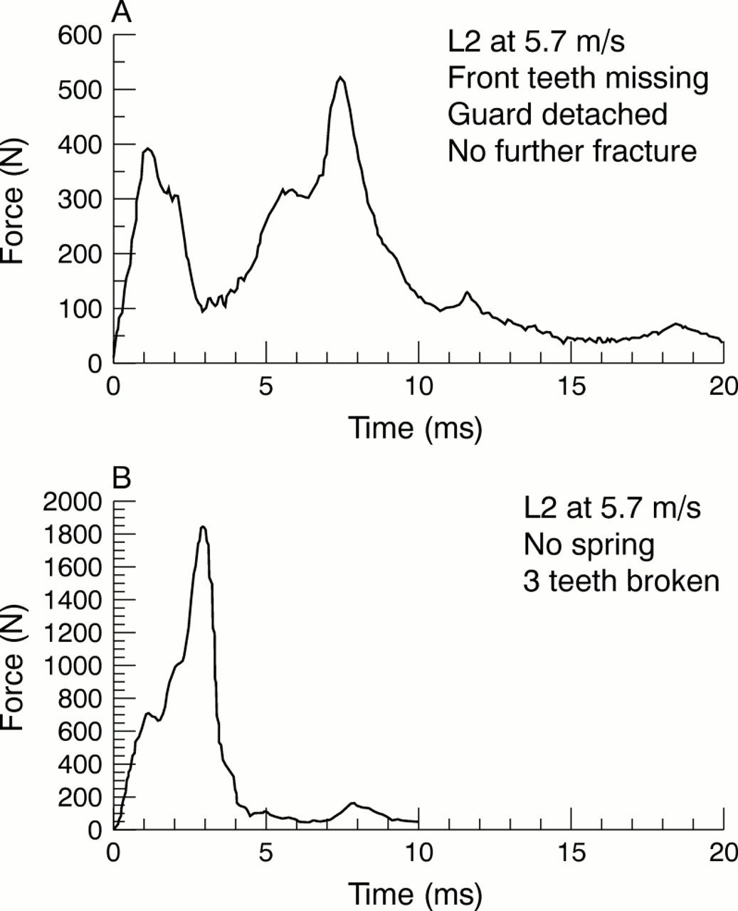
Impact tests at 5.7 m/s of mouthguard L2. (A) Front four teeth missing; (B) without spring.
Comparing guard L2 at 5.7 m/s in fig 4⇑ with fig 6A⇑ shows that missing teeth reduce both the initial and secondary stiffness as the peaks are reduced from 850 to 400 N and 1350 to 530 N respectively.
With no spring mounting present (fig 6B⇑), the inertial peak and secondary peaks are combined to give a massive peak force of 1850 N at 5.7 m/s and three broken teeth. Hence the spring mounting can be seen to be very significant in reducing the peak force during the impact event.
CONCLUSIONS
These results are interesting in their own right. However, recommendations that may improve the performance of future mouthguards are more appropriate in this publication.
The impact event of a spring mounted model jaw, with and without a mouthguard fitted, comprises an initial inertial peak followed by a secondary peak.
Good mouthguards that remain attached and prevent tooth fracture help to retain the structural integrity of this impact target. This in turn means that high transient forces are developed in the impactor.
Guard detachment and tooth fracture are usually related to a reduced maximum load during the second peak which is therefore indicative of a loss of integrity in the model jaw.
The spring mounting is very effective at minimising the maximum force developed and confirms the value of “riding the punch” in quantitative terms, reducing the peak force from 1850 N to 1350 N.
The initial peak is very predictable but not a good guide to overall mouthguard performance. The second peak and the area under it offer some potential as a quantitative assessment of mouthguard performance.
FURTHER WORK
Attachment of conductive strips to the ceramic teeth will enable the precise moment of tooth fracture to be established, and finite element modelling will attempt to predict the force levels on this simplified assembly. The acquisition of an injection moulding tool will enable the rubber jaw to be made more realistic, and the finite element models with more realistic tooth shapes will be developed once good agreement with the simple models has been established.
Acknowledgments
This work could not have been completed without the assistance of Gordon Imlach at the Open University and Dr Peter Reed of Queen Mary and Westfield College and latterly the University of Twente who made the equipment available and provided the breakthrough in the interpretation of the results.
Linked Articles
- Original article